26 Results
View results:
Sort by:

When calculating regular structures, data input is often not complicated but time-consuming. Input automation can save valuable time. The task described in the present article is to consider the stories of a house as single construction stages. Data is entered using a C# program so that the user does not have to enter the elements of the individual floors manually.

In RFEM 6 it is possible to save selected objects (as well as whole structures) as blocks and reuse them in other models. Three types of blocks can be distinguished: non-parameterized, parameterized, and dynamic blocks (via JavaScript). This article will focus on the first block type (non-parameterized).

When modeling structural bearing systems, especially hall structures, some substructures of a foundation with no influence on the rising structure are not modeled in RFEM/RSTAB. In the case of hall structures, these are, for example, reinforced concrete floor slabs, strip foundations, and the ties between column foundations.

The additional loads from self‑weight are usually composed of several layers; for example, classic floor and ceiling layers in buildings, or road coatings for bridge constructions. When defining load definitions in RFEM and RSTAB, you can use the multi-layer load to define the individual layers with thickness and specific weight.

You can use the "Free Circular Load" option in RFEM to apply a partial uplift force to a cone‑shaped floor slab. It can be defined as linearly variable. The definition of center C and the outer boundary R can be specified easily, using the select function.

The new "Result Beam" member type in RFEM 5 allows you to determine the load sums of individual floors easily. To do this, model a member in the relevant floor or in all floors, then specify the relevant walls as inclusive objects in the parameters of the result beam. RFEM then integrates the surface internal forces into member internal forces.
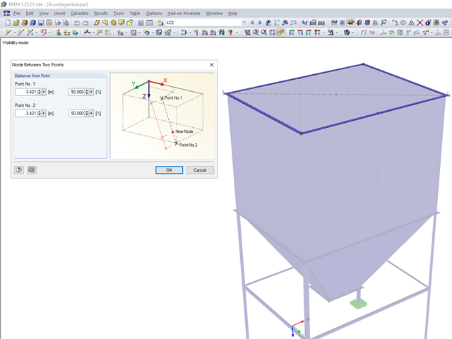
Until now, if you wanted to determine the centroid of a rectangle, it was necessary to define a line from one corner point to the diagonally opposite point. You obtained the centroid by dividing this line. In RFEM 5 and RSTAB 8, you now have the possibility to create a node between two points. Thus, it is sufficient to select the corner points; then you can determine the distance in absolute or relative values.
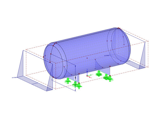
A fluid with a constant density in a homogeneous gravity field exerts a hydrostatic pressure on its comprehensive container wall according to Pascal's law.

Sometimes a structure needs reinforcement in cases where a new floor is being added, or when an existing member is found to be under design due to a hard-to-predict loading assumption. In many cases, the structural member may not be easily replaced, and reinforcement is implemented to meet the new loading requirement.
Settlement within a structural system can also affect the surrounding structures. The adjacent settlement of separated slabs can be considered with RF-SOILIN using a small trick.

Describing the procedure for the serviceability limit state design of a floor slab made of steel fiber reinforced concrete. This article shows how to perform the corresponding design for the SLS by means of the iteratively determined FEA results.
.png?mw=640&hash=bfebd5ea2d4f77a817fa987424a23a799b3fe711)
When you perform the subsequent modeling of a beam under an existing floor, the first issues that arise are which forces should be transferred between the downstand beam and the floor, and whether a composite effect is the goal. In this case, the floor should rest on the downstand beam without a composite.

Steel-fiber-reinforced concrete is mainly used nowadays for industrial floors or hall floors, foundation plates with low loads, basement walls, and basement floors. Since the publication in 2010 of the first guideline about steel-fiber-reinforced concrete by the German Committee for Reinforced Concrete (DAfStb), a structural engineer can use standards for the design of the steel fiber-reinforced concrete composite material, which makes the use of fiber-reinforced concrete increasingly popular in construction. This article describes the nonlinear calculation of a foundation plate made of steel fiber-reinforced concrete in the ultimate limit state with the FEA software RFEM.
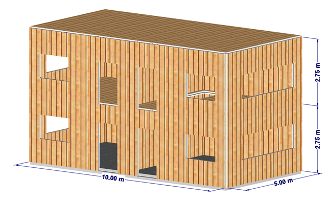
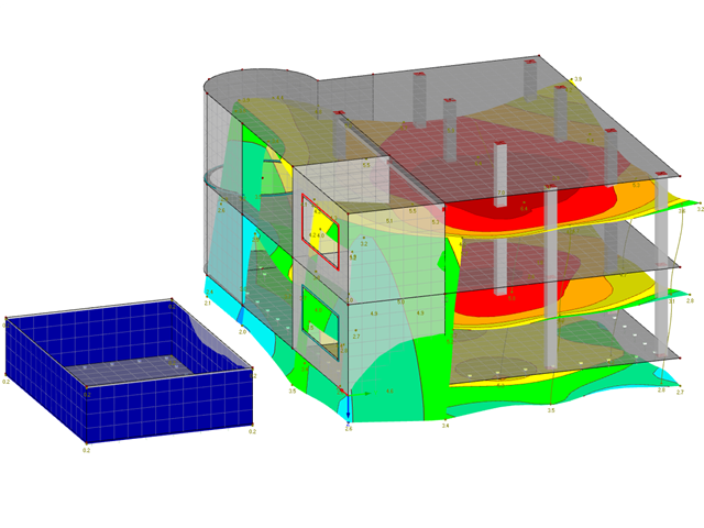
This article shows the effect of the different stiffnesses of the timber panel walls on the floor plan.

In RF-PUNCH Pro, enlarged column heads can be arranged at point-supported punching shear points, thus increasing the shear force resistance of a reinforced concrete floor. In the following article, we will show the punching shear design with the optional application of an enlarged column head.

Determining the Material Properties of Steel-Fiber-Reinforced Concrete and Their Application in RFEM
Steel-fiber-reinforced concrete is mainly used nowadays for industrial floors or hall floors, foundation plates with low loads, basement walls, and basement floors. Since the publication in 2010 of the first guideline about steel-fiber-reinforced concrete by the German Committee for Reinforced Concrete (DAfStb), a structural engineer can use standards for the design of the steel fiber-reinforced concrete composite material, which makes the use of fiber-reinforced concrete increasingly popular in construction. This article explains the individual material parameters of steel-fiber-reinforced concrete and how to deal with these material parameters in the FEM program RFEM.
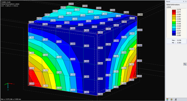
The deformations of the FE nodes are always the first result of an FE calculation. It is possible to calculate strains, internal forces, and stresses based on these deformations and the stiffness of the elements.

According to Clause 7.3.2 (2), standard DIN EN 1992-1-1 requires: "In profiled cross‑sections like T‑beams and box girders, the minimum reinforcement should be determined for the individual parts of the section (webs, flanges)." In the case of a floor beam with a T‑section, the minimum reinforcement should be determined for both flanges and the web if the corresponding partial cross‑sections are in the tension area. Image 01 shows the division into partial cross-sections.
This article describes the determination of force coefficients using a wind load and the calculation of a stability factor due to lateral-torsional buckling.
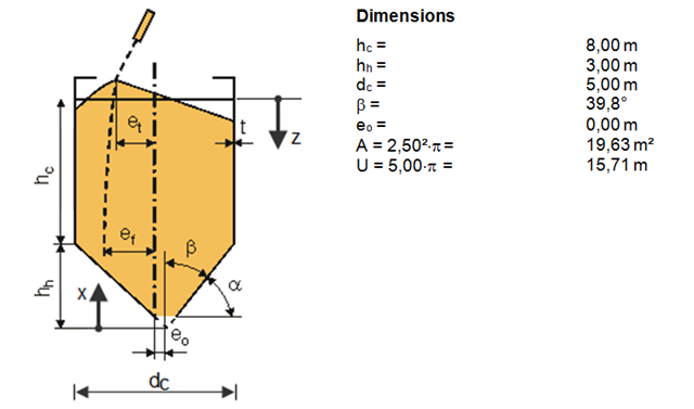
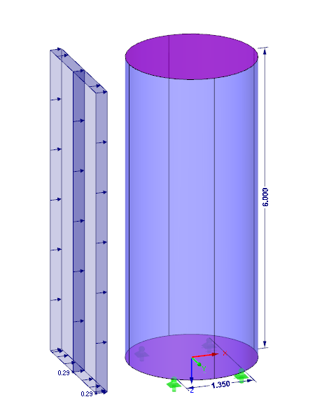
The previous article described the actions on silos according to DIN EN 1991-4. On an example of a free standing cylindrical silo for cement with a conical hopper, filling loads of the silo hopper were calculated.
![Structural System for Schöck Isokorb® Type K from [1]](/en/webimage/009555/2419353/01-en-png.png?mw=640&hash=c76563b459152b19c98197ea6ba342be89d9a5bc)
Heat loss due to external components without thermal decoupling of the internal components is enormous. For this reason, external structural components are thermally separated from the building envelope using a special built-in component. For the connection of a balcony slab with a reinforced concrete floor, Schöck Isokorb® or HALFEN HIT Insulated Connection can be used, for example. For the design of such built-in components, the respective technical approval must be taken into account. The following article shows an example of considering Schöck Isokorb® in the FEM calculation.
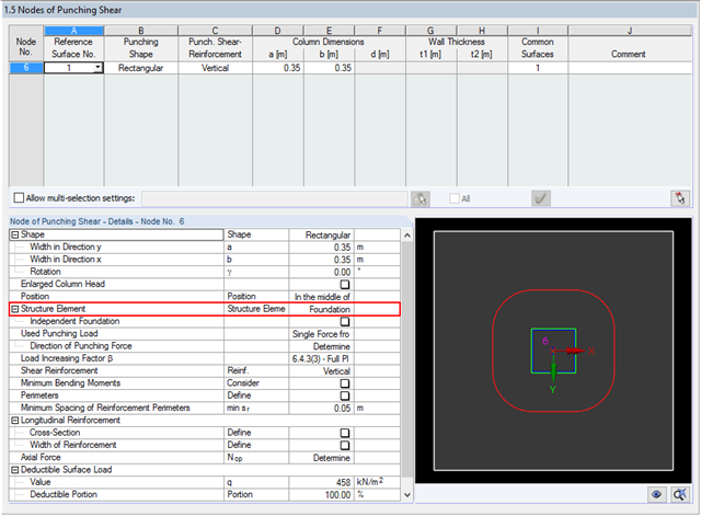
The RF‑PUNCH Pro add‑on module allows you to perform the punching shear design of floor slabs and foundation plates according to EN 1992‑1‑1. In the case of a floor slab, the basic control perimeter is applied according to 6.4.2 (1), EN 1992‑1‑1 [1] at a distance of 2d from the loaded area.

Nodal supports are usually defined with regard to the global axis system. However, it is sometimes necessary to rotate the nodal support. For example, for a floor slab with a pile foundation. For geological reasons, the piles do not rest in the ground vertically, but in an inclined position. Each end point of the piles has a nodal support that can only absorb forces along the pile foundation direction. Therefore, rotating the nodal support is required. Various options for this are described in previous posts.

Silos are used as large containers for storage of bulk materials such as agricultural products or source materials as well as intermediates of industrial production. The structural engineering of such structures requires a precise knowledge of the stresses due to particulate solids in the building structure. The standard EN 1991‑4 "Actions on Silos and Tanks" [1] provides the general principles and requirements for determining these actions.

For structural components consisting of slabs, it is necessary to perform shear design on the locations with concentrated load introduction, applying the punching shear design rules according to Sect. 6.4 of EN 1992‑1‑1 [1]. The concentrated load introduction is present on the individual locations, for example by columns, concentrated load, or nodal supports. In addition, the end of linear load introduction on slabs is also regarded as concentrated load introduction. For example, this includes wall ends, wall corners, and ends or corners of line loads and line supports. You can perform the punching shear design for floor slabs or foundations, considering the existing available plate topology about the designed node of punching shear. The punching shear design according to EN 1992‑1‑1 checks that the acting shear force vEd does not exceed the resistance vRd.
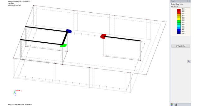
The RF-PUNCH Pro add-on module allows you to perform punching shear design of slabs and foundation plates (floor slabs) on wall ends and wall corners.